How to build a power transformer
Posted: June 02, 2025
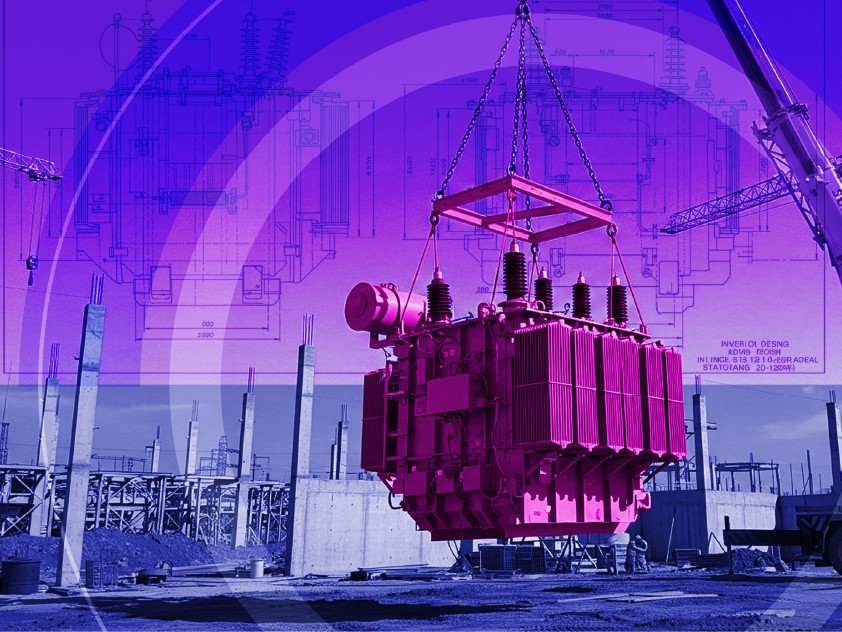
Large power transformers are a vital part of any electric grid. It’s through them that the electricity generated by power plants is “stepped up” to the high voltages of cross-country transmission lines, and also through them that the electricity roaring along those lines is “stepped down” to the lower voltages of neighborhood distribution lines.
They are the grid’s equivalent of a foreign exchange booth at an airport, swapping unusable money for more useful curren(t)cies.
Except right now, new booths are proving hard to find. Globally, over the last five years transformer manufacturing lead times have climbed from a few weeks to 2–3 years and prices have risen 74–106%. In the UK, the transformer shortage is contributing to a 10- to 15-year wait to connect new renewables plants to the grid.
Our Industrial Life
Get your bi-weekly newsletter sharing fresh perspectives on complicated issues, new technology, and open questions shaping our industrial world.
The explosion in renewable electricity generation is driving some of the shortage, but it’s not the only reason for it. Transformers are often custom-built according to the requirements of specific substations—in the U.S., for instance, there are 80,000 small transformer varieties. With the modal age of U.S. transformers sitting between 37-39 years old, many of these transformers increasingly need replacing.
In other words, despite the science behind transformers going back to the 1830s, and despite their critical role in the grid, the manufacturing of transformers remains a major bottleneck in the modernization of the grid.
Here’s how these exquisitely constructed pieces of machinery are built.
Step 1: Build the steel core

At the heart of a transformer is a steel core. In a working transformer, this core plays a crucial role in the efficient transfer of electrical current.
To maximize the electromagnetic efficiency of the transformer, the core consists of thin sheets of grain-oriented electrical steel (GOES). As opposed to regular steel, which is an alloy of iron and carbon, electrical steel is made of iron and silicon.
“The production process for GOES […] is similar to that of carbon steel but requires a higher level of process control at each stage,” found a U.S. government report into transformers. The report also concluded that the country’s sole-remaining GOES mill was outdated, and that the majority of the high-grade GOES imported into the country came from South Korea.
To further increase efficiency, each sheet of electrical steel is coated in insulation. The sheets are then bound tightly together to form the laminated core.
Step 2: Coil winding
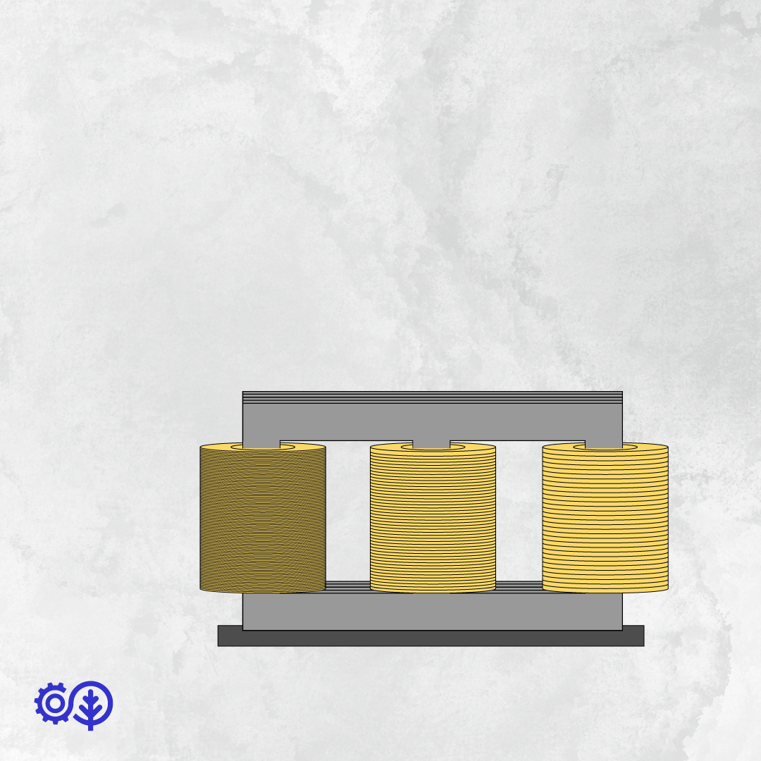
Separate coils—made of copper or, increasingly, aluminum—are wound around the columns of the core. The core-coil unit will do the “transforming” that gives this machine its name.
As electrical current flows through the first coil, it induces a magnetic flux through the steel core, which in turn induces current in the second winding. The voltage that the second winding conducts is determined by the ratio between the number of coils in the first and second windings. Because voltages can fluctuate, transformers are installed with devices (called tap changers) that can adjust the number of windings of coils while the transformer is in operation.
Much like the laminated steel core—and for the same reasons of electromagnetic efficiency—coils in large power transformers do not consist of single pieces of solid metal, but an intricately entwined cable of individually insulated copper strands. Each strand, as one manufacturer explains, “consecutively and repeatedly assumes every possible position inside the cable.”
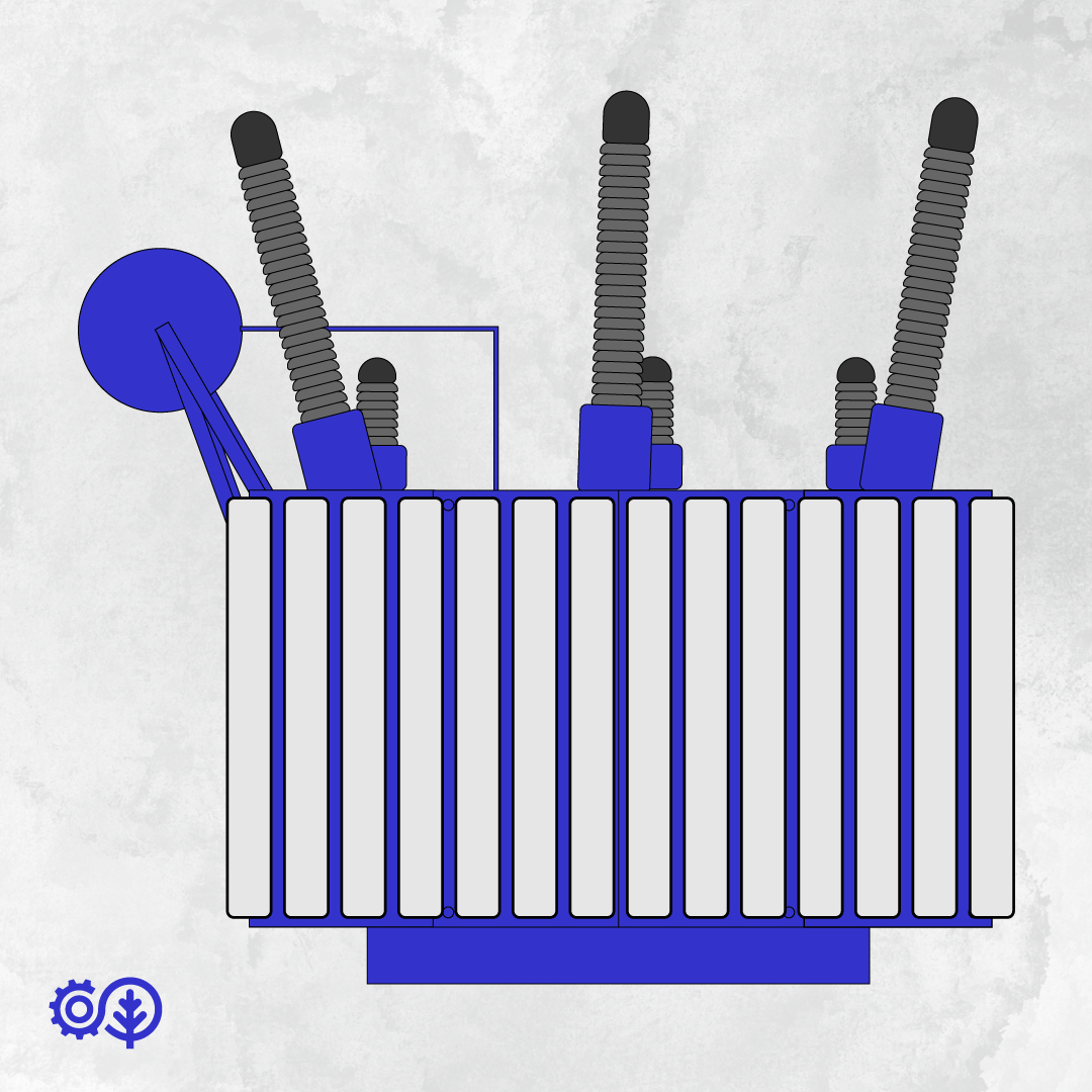
Step 3: Tank up the core-coil unit

Once the core-coil unit has been assembled, it is thoroughly cleaned and extra insulation, made of paper, is added to the unit. The whole thing is then baked in a vacuum-pressure oven, which dries out the unit at a low temperature.
To avoid absorbing moisture from the air, the unit is then promptly lowered into a steel tank, and the tank is filled with insulating oil.
The tank is also fitted with drain valves, explosion vents, and bushings. These oddly shaped, antennae-like things will connect the transformer to the electrical lines of the grid.
Step 4: Test and transport
The transformer is tested at several points during the manufacturing process, but it is most thoroughly tested once finished. Transformer factories even have high-voltage test halls—which mimic the conditions of the grid—especially for this purpose.
Although modern transformers are very efficient, some waste heat is nonetheless generated. For this reason, large power transformers are also fitted with external radiators that help cool the insulating oil.
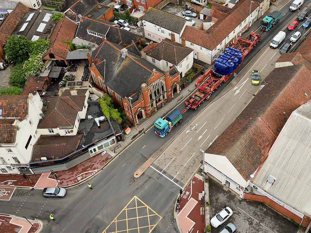 A super grid transformer travelling with police escort through the British town of Bridgwater. Despite being under 9 meters long, it weighs 174 tonnes—equivalent to 30 African elephants. Source: National Grid
Once the transformer is deemed grid-worthy, it then has to be transported—no mean feat considering that large power transformers weigh hundreds of tonnes. “A lot of work goes into transformer deliveries, long before any electrons pass through them,” said Roisin Quinn, director of asset operations at the UK’s National Grid, in a press release about 2024 transformer deliveries. “Multiple teams across National Grid and its supply chain are involved in moving and installing these huge devices.”
After installation at a substation, large power transformers will, with proper maintenance, run almost without interruption for decades.